|
A Project by:
Tony
/ I2TZK, Frank
/ K7SFN , Dinesh
/ VU2FD
This project is
revised as: AAZ-0217
AAZ-0713A:
35MHZ Antenna Analyzer:
AAZ-0713A:
AAZ-0713A is designed to work as a
standalone USB Antenna Analyzer like AAZ0912 and suitable to works with a Graphic
LCD Display.
A PC program is available for
using AAZ-0713A as a PC based USB antenna analyzer, like our most
popular AAZ-0912. Firmware for Graphic CPU
and Antenna Analyzer - 0713 are developed by Tony/I2TZK.
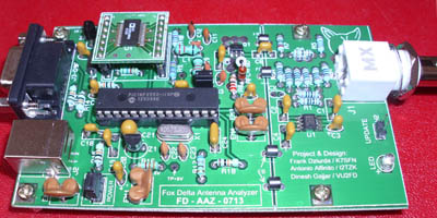
AAZ-0713A is a simple single
board antenna analyzer using DDS signal as a source and a return
signal from antenna is used for measurement by a Log Amplifier AD8307
AAZ-0713A is Project
"INFINITY" Module:
Graphic CPU which may be used
with this
Antenna Analyzer is a core of
our "INFINITY" Project and is
developed keeping in mind that we use same CPU/LCD/Hardware for
various Purposes or Projects, saving a lot of money in
hardware.
AAZ-0713A is designed in two
parts:
1. Graphic CPU
Board: GCPU-0613 and
2. Antenna Analyzer Board:
AAZ-0713A
A D9 Male to male cable
(supplied with Graphic CPU KIT) is required to interconnect two
units. Communication from CPU to Antenna Analyzer is by way of
serial data fed to USB port. (It uses I2C lines of Graphic CPU for
this purpose and USB data lines of AAZ-0713)
Antenna Analyzer AAZ-0713A has
more possibilities:
1. USB Interface: for your PC
(same like AAZ-0912)
2. Use with Graphic LCD CPU-0613
to operate without a PC.
3. with a BT
interface, use your Android phone as display
Compatibility with AAZ-0912:
If you like to have a Graphic
Display for your AAZ-0912 board, you
need not buy or build this AAZ-0713. Just make yourself a simple USB
to D9M cable, do a small modification on AAZ-0912 board and you are
ready to use Graphic LCD Display for your AAZ-0912.
Modification to AAZ-0912 board
as suggested by Tony/I2TZK
is here: (these are also implemented on this
AAZ-0713 design): 
Design Change from Last Version
of AAZ-0713:
AAZ-0713A uses ERA-3SM from
Mini Circuits in place of ADA4789 amplifier. No other design
changes.
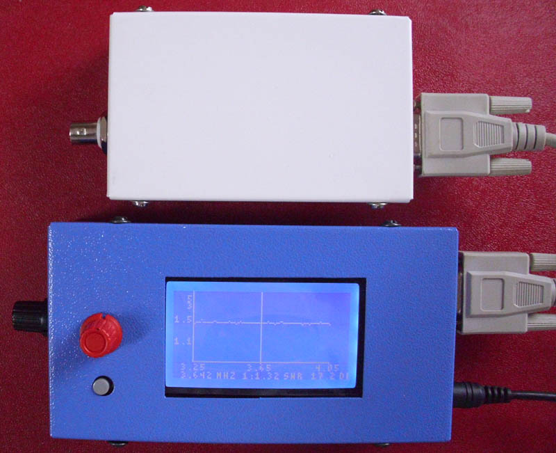
Antenna Analyzer
AAZ-0713A and Graphic
CPU-0613:

Click above picture for
larger view
Antenna
Analyzer- 0713A: Standalone USB
Click above picture for
larger view
Graphic Antenna Analyzer
Hardware Details:
|